Information on the most widely used ASTM standards within the materials testing industry

-
Products
- > Universal Testing Machine
- > Dynamic Fatigue Testing Machines
- > Biaxial & Triaxial Testing Machines
- > Test Fixtures
- > Plastic Pipe Industry Testing
- > Compression Testing Machine
- > Torsion Testing Machine
- > Impact Testing Machine
- > Hardness Tester
- > Industrial Specialized Testing
- > Customized Testing Machine
-
Application

Descriptions of the most prominent lSO standards within the materials testing industry

Standards including EN, DIN, JlS, and more

Mechanical testing of polymer materials in the automotive industry is directly related to the safety of components and the reliability of the entire vehicle. UnitedTest can cover mechanical performance testing for automotive interior and exterior parts, as well as functional components, adapting to automaker standards and providing comprehensive testing solutions including tensile, impact, and fatigue tests.

Mechanical testing in the battery industry determines the tensile and puncture resistance of core components such as separators and electrodes, directly affecting battery safety and cycle life. UnitedTest can cover full-dimensional mechanical testing of battery materials, compatible with national and international standards, and provide customized testing solutions.

Mechanical testing in the consumer goods industry determines product durability and safety, such as impact resistance for toys and fatigue resistance for home appliances, making it core to compliance and quality. UnitedTest can cover mechanical tests for all categories of consumer goods, including tensile, impact, and hardness tests, compatible with national and international standards, and offers customized testing solutions.

In the field of medical and biomedical sciences, mechanical testing determines the safety and compatibility of implanted devices and biomaterials, making it a core part of regulatory approval. UnitedTest can cover a full range of tests including tensile, fatigue, and wear tests, compatible with national and international standards, and provides customized biomechanical testing solutions.

Material strength is a course that most engineering fields are required to study in university education. This interesting course is very practical and makes use of testing equipment in the materials laboratory.

Mechanical testing of industrial products and components is essential to ensure their load-bearing, fatigue resistance, and impact resistance, directly preventing production accidents and ensuring stable operation of equipment. UnitedTest can cover a full range of tests including tensile, hardness, and fatigue, complying with national and international standards, and provides customized industrial mechanical testing solutions.

Mechanical testing in the plastic pipe industry determines ring stiffness, impact resistance, and tensile performance, directly preventing pipe bursts and deformation risks. UnitedTest can cover full-dimensional mechanical testing of pipes, complies with ISO,ASTM,EN et.c, international standards, and provides customized testing solutions.

In the construction engineering and building materials industry, mechanical testing determines the compressive and tensile properties of materials such as concrete and steel, which is core to ensuring the safety and durability of buildings. UnitedTest can cover the full range of building material mechanical tests, complies with ISO, ASTM international standards, and provides customized testing solutions for compressive, tensile, and other properties.

Mechanical testing in the food and beverage industry involves the compressive and tensile performance of packaging and the safety of food texture, directly ensuring storage, transportation safety, and the eating experience. UnitedTest can cover all-dimensional mechanical testing for packaging and food texture, comply with national and international standards, and provide customized testing solutions.

Mechanical testing in the packaging industry determines the packaging's resistance to compression, impact, and tension, directly ensuring the safety of contents during storage and transportation. UnitedTest can cover comprehensive mechanical testing for packaging, complying with ISO, ASTM Standards, and provides customized testing solutions for compression, drop, tear, and more.

Mechanical testing in the transportation industry concerns the load-bearing and fatigue resistance performance of core components such as vehicles, tracks, and containers, directly ensuring transport safety and equipment durability. UnitedTest can cover mechanical testing for all types of transportation materials, complying with national and international standards, and provides customized testing solutions including tensile, fatigue, and impact tests.

Metallurgical testing examines the properties of metallic materials to determine if a particular metal is appropriate for its intended use.

Testing of polymer materials covers mechanical, thermal, and chemical properties, verifying strength, heat resistance, composition, and ensuring product quality and compliance.

UnitedTest offer world-class testing solution in testing for polymeric materials, including elastomers, thermoplastics, composites, coatings, and structural adhesives in a variety of industries.

Testing of rubber and elastomers is used to assess the various properties and performance of materials under different conditions. This is crucial for ensuring the safety, functionality, and quality of rubber and elastomer products used in industries such as automotive, construction, consumer goods, and aerospace.

Conduct adhesive testing using various testing methods to determine their performance and characteristics in applications across multiple industries such as aerospace, automotive, construction, packaging, industrial, medical, and energy, thereby supporting application development and quality assurance.

UnitedTest supply machine and testing solution for tension, compression, fracture toughness, direct shear, triaxial and ultrasonic velocity are common concrete and rock testing applications.

UnitedTest has helped a number of companies involved in the wood, paper, cardboard, and corrugated industry with their testing needs. Our materials testing systems are capable of testing raw materials, components, and finished products.

UnitedTest testing system is trusted by leading medical device manufacturers, universities, and medical research laboratories worldwide. Whether testing tissues or bioresorbable materials, stents, or sutures, UnitedTest offers a variety of single-actuator and dual-actuator systems to meet your biomedical testing needs.

Mechanical testing in the textile fabric industry determines core properties such as fabric tensile strength, tear resistance, and wear resistance, directly affecting product durability and safety. UnitedTest can cover comprehensive mechanical tests for textiles, complying with national standards / ISO standards, and provides customized testing solutions including tensile, tear, and puncture tests.

The mechanical testing of industrial components directly determines the load-bearing, fatigue resistance, and wear resistance of the parts, helping to avoid equipment failure risks. UnitedTest can cover a full range of tests including tensile, hardness, and fatigue, is compatible with ISO/ASTM/GB standards, and provides customized mechanical testing solutions for industrial components.

Mechanical testing in the glass-ceramics industry determines core properties such as flexural strength, hardness, and fracture toughness, directly helping to avoid brittleness and failure risks. UnitedTest can cover comprehensive testing for flexural strength, hardness, and fracture toughness, compatible with national and ISO/ASTM standards, and provides customized testing solutions.

Tensile test evaluates material resistance to stretching, measuring strength/elongation critical for quality control. UnitedTest offers universal tensile testers (10-600KN) compliant with ASTM/ISO standards, providing tailored solutions for metals, polymers, medical & industrial materials.

Compression test assesses material resistance to compressive loads, measuring strength/deformation critical for quality validation. UnitedTest offers compression testing machines compliant with ASTM/ISO standards, providing tailored solutions for concrete, plastics, metals and industrial components.

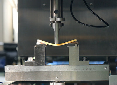
Flexural & Bend tests evaluate material resistance to bending forces, measuring strength, stiffness and ductility for quality assurance. UnitedTest provides flexural testing machines (3-point/4-point bend) compliant with ASTM/ISO standards, offering tailored solutions for composites, plastics, metals and construction materials.

Torsion Test evaluates material resistance to rotational forces, measuring torsional strength/ductility critical for fasteners, insulators, shafts. UnitedTest offers torsion testers compliant with ASTM A938/ISO 16047, providing tailored solutions for automotive, aerospace, fastener industries.

Fatigue Test assesses material durability under cyclic loading, critical for predicting service life of industrial components. UnitedTest offers fatigue testing systems (axial/bending/torsion) compliant with ASTM E466/ISO 12106, providing tailored solutions for automotive, aerospace and manufacturing sectors.

Peel Test measures material adhesion strength by evaluating resistance to peeling forces, critical for adhesives, films, packaging. UnitedTest offers peel testers compliant with ASTM D903/ISO 8510, covering 90°/180° peel tests, and tailored solutions for packaging, automotive, textile industries.

Impact Test evaluates material resistance to sudden shock loads, critical for assessing toughness and fracture risk. UnitedTest offers impact testers (Charpy/Izod/fall weight) compliant with ASTM E23/ISO 148, providing tailored solutions for metals, plastics, glass and industrial components.

Tear & Shear Test evaluates material resistance to tearing and shearing forces, measuring critical strength parameters for quality control. Tear tests (Elmendorf/trouser/trapezoidal) assess resistance to crack propagation in films/fabrics, while shear tests measure resistance to parallel forces in joints/bolts. UnitedTest provides universal testing machines (10KN-600KN) with specialized fixtures for both tests, compliant with ASTM D624/D3164 and ISO standards, serving automotive, packaging and construction industries.

Hardness test measures material's resistance to permanent indentation, critical for quality control. UnitedTest offers universal hardness testers (Rockwell/Brinell/Vickers) compliant with ASTM/ISO standards, plus tailored hardness testing solutions for diverse industrial needs.

Biaxial/triaxial tests evaluate material performance under multi-axis loads, critical for biomaterials, metals and composites. UnitedTest provides compliant testing machines (ASTM/ISO) for planar biaxial, static/fatigue triaxial tests, with tailored solutions for industrial & biomedical needs.

Friction and wear tests assess material resistance to friction, abrasion and wear, critical for industrial material performance validation. UnitedTest offers tribometers compliant with ASTM G99/ISO standards, covering pin-on-disk, four-ball tests, and tailored friction & wear testing solutions for diverse industries.

Pressure test evaluates material/component resistance to static/dynamic pressure, critical for sealing, strength and safety validation. UnitedTest offers pressure testing machines compliant with ASTM/ISO standards, covering burst, hold-pressure tests, and tailored solutions for industrial, automotive & medical sectors.

Fire test assesses material flammability, heat resistance and fire-retardant performance, critical for safety compliance across industries. UnitedTest offers fire testing equipment compliant with ASTM/ISO/UL standards, providing tailored fire test solutions for building materials, plastics and industrial components.

Non-destructive Test (NDT) evaluates material/component integrity without damage, critical for safety & quality across industries. UnitedTest offers ultrasonic/X-ray/magnetic particle NDT equipment compliant with ASTM/ISO standards, plus tailored NDT solutions for aerospace, automotive & manufacturing sectors.
-
Technical Support

Browse the video library to see theUnitedTest system in action

View our after-sales service

Go to our download center to download

Frequently Asked Questions
- Company
- News
- Contact
- Home
-
Products
+
- Universal Testing Machine +
- Dynamic Fatigue Testing Machines +
- Biaxial & Triaxial Testing Machines
- Test Fixtures +
- Plastic Pipe Industry Testing +
- Compression Testing Machine +
- Torsion Testing Machine +
- Impact Testing Machine +
- Hardness Tester +
- Industrial Specialized Testing +
- Customized Testing Machine
- Application +
- Technical Support +
- Company
- News +
- Contact